
This design note describes a new approach to precision LVDT signal conditioning that combines an LTC1967 RMS to DC converter with a separate phase detector circuit. This approach eliminates the losses and errors associated with traditional demodulation methods and also eliminates the complexity and cost associated with phase-locked loops.
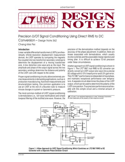
This document presents an application design note (DN362) on achieving precise Linear Variable Differential Transformer (LVDT) measurements. It proposes using the LTC1967 true RMS to DC converter to eliminate errors associated with traditional demodulation methods, such as phase lag and timing jitter.
The text details a specific circuit implementation involving a Schaevitz E-100 LVDT driven by an LT1807 amplifier. A separate phase detector using LT1720 comparators determines the core polarity. The note includes instructions for calibrating the amplitude output to minimize errors caused by flux leakage in the transformer.
The maximum recommended frequency is 10kHz.
The LVDT has a linear range of +2.5mm.
The output should be adjusted to approximately 2V.