
This is a design note about a low-power, direct-to-digital IF receiver. The receiver uses a variable gain amplifier + analog-to-digital converter (VGA + ADC) combination circuit that preserves the IF receiver dynamic range over a 31dB gain adjustment range and effectively demodulates and digitizes both the I and Q signals.
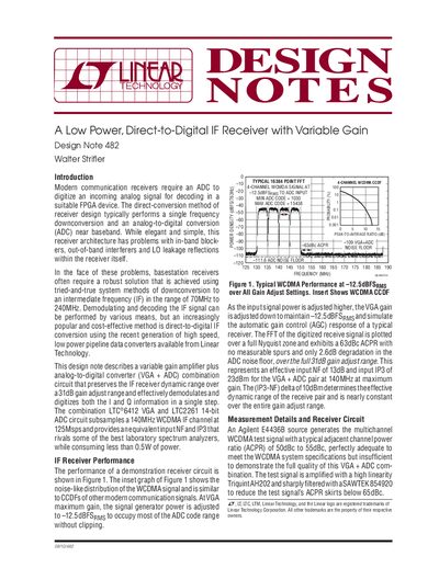
Modern communication receivers often require robust solutions using intermediate frequency (IF) downconversion. This document presents a direct-to-digital IF receiver architecture utilizing the LTC6412 Variable Gain Amplifier (VGA) and the LTC2261 14-bit Analog-to-Digital Converter (ADC). The circuit is designed to preserve dynamic range over a 31dB gain adjustment while effectively demodulating In-phase and Quadrature information in a single step.
The total power consumption for the combination is less than 490mW.
The circuit provides an effective input NF of 13dB and an input IP3 of 23dBm.
Charge impulses need to dampen during a sampling window of 4ns.