
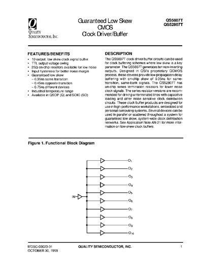
The QS5807T and QS52807T are low‑skew clock driver/buffer ICs designed for high‑performance workstations, embedded and personal computing systems. They provide ten non‑inverting outputs with guaranteed skew of 0.35 ns for same‑transition signals and 0.45 ns for opposite‑transition signals, making them suitable for precise clock distribution networks.
The document lists the pinout, absolute maximum ratings, DC electrical characteristics, power‑supply requirements, and switching performance. It also includes test circuit diagrams, waveform examples, and ordering information for both QSOP and SOIC packages.
| Output skew (same transition) | 0.35 ns |
|---|---|
| Output skew (opposite transition) | 0.45 ns |
| Number of outputs | 10 |
| Supply voltage range | -0.5 V to 7.0 V |
The QS5807T guarantees a skew of 0.35 ns for same‑transition signals and 0.45 ns for opposite‑transition signals.
The QS5807T provides ten non‑inverting output pins.
The device operates with a supply voltage from –0.5 V up to 7.0 V.