
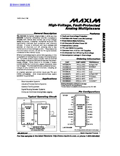
The MAX388 and MAX389 are high‑voltage, fault‑protected analog multiplexers that use a series N‑channel/P‑channel FET structure to limit leakage and protect both the device and connected signal sources. They turn off all channels when power is removed, allowing only nanoampere‑level leakage even with input voltages up to +100 V.
These devices operate from +4.5 V to +18 V supplies, support TTL and CMOS logic levels, and provide break‑before‑make switching with typical 600 ns channel‑to‑channel transition time. They are suited for data‑acquisition systems, industrial process control, avionics test equipment, and signal routing between systems.
| Operating Temperature Range | -40 °C to +125 °C |
|---|---|
| Leakage Current (OFF) | nanoamperes |
The devices turn off a channel when an over‑voltage signal up to +100 V is applied to an analog input or output.
Channel‑to‑channel switching time is typically 600 ns, including about 200 ns of break‑before‑make delay.