
The document describes the complete 16-bit imaging signal processor AD9826 by Analog Devices. The processor features a 16-bit 15 MSPS A/D converter, capable of 3-channel 16-bit operation up to 15 MSPS. It also includes programmable gain and offset, as well as an internal voltage reference.
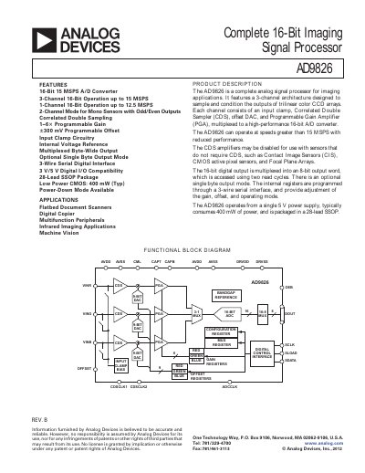
The AD9826 is a complete 16‑bit imaging signal processor designed for color CCD arrays. It features a three‑channel architecture, each channel with an input clamp, correlated double sampler, programmable offset DAC and programmable gain amplifier, all multiplexed to a high‑performance 16‑bit A/D converter.
The device operates from a single 5 V supply, consumes about 400 mW in 3‑channel mode, and supports up to 30 MSPS conversion in CDS mode. It is offered in a 28‑lead SSOP package and is used in flatbed scanners, digital copiers, machine‑vision and infrared imaging applications.
| Maximum conversion rate (3‑Channel Mode with CDS) | 30 MSPS |
|---|---|
| ADC resolution | 16 bits |
| Power consumption (3‑Channel Mode) | 400 mW |
| Package | 28‑Lead SSOP |
| Input signal range (with input clamp) | 0 V to 4 V |
The AD9826 can convert up to 30 MSPS in 3‑Channel mode with CDS.
The ADC provides a 16‑bit resolution.
Typical power dissipation is 400 mW in 3‑Channel mode.
The linear input range is from 0 V to 4 V.