
The AD9943/AD9944 are complete analog signal processors for CCD applications. They feature a 25 MHz single-channel architecture designed to sample and condition the outputs of interlaced and progressive scan area CCD arrays. The signal chain for the AD9943/AD9944 consists of a correlated double sampler (CDS), 6 dB to 40 dB 10-bit variable gain amplifier (VGA), low noise optical black clamp circuit, preblanking function, 10-bit (AD9943), 12-bit (AD9944) 25 MSPS A/D converter, 3-wire serial digital interface, 3 V single-supply operation, and space-saving 32-lead 5 mm × 5 mm LFCSP package.
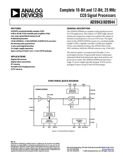
The AD9943/AD9944 are complete analog signal processors for CCD applications. They provide a 25 MHz correlated double sampler, a digitally controlled variable gain amplifier, and a black level clamp, with the AD9943 delivering 10‑bit resolution and the AD9944 delivering 12‑bit resolution. The devices operate from a single 3 V supply and communicate via a 3‑wire serial digital interface.
Key specifications include a 25 MHz maximum clock rate, 79 mW normal power consumption, and operation over –20 °C to +85 °C. They are supplied in a space‑saving 32‑lead LFCSP package and are intended for digital still cameras, video camcorders, portable CCD imaging devices, and CCTV cameras. The datasheet also provides pin configurations, timing diagrams, absolute maximum ratings, and grounding recommendations.
| Maximum Clock Rate | 25 MHz |
|---|---|
| Resolution (AD9943) | 10 bits |
| Resolution (AD9944) | 12 bits |
| Power Consumption (Normal Operation) | 79 mW |
| Operating Temperature Range | -20 °C to +85 °C |
| Supply Voltage | 3.0 V |
| VGA Gain Control Resolution | 1024 steps |
| Maximum Input Range before Saturation | 1.0 Vp-p |
| Maximum Serial Clock Frequency | 10 MHz |
The maximum input range before saturation is 1.0 Vp‑p.
The VGA gain control provides 1024 discrete steps.
The serial interface can operate up to a maximum SCK frequency of 10 MHz.