
The LMD18201 is a 3A H-Bridge designed for motion control applications. It is built using a multi-technology process which combines bipolar and CMOS control circuitry with DMOS power devices on the same monolithic structure. The H-Bridge configuration is ideal for driving DC and step-per motors. The LMD18201 accommodates peak output currents up to 6A. Current sensing can be achieved via a small sense resistor connected in series with the power ground lead. For current sensing without disturbing the path of current to the load, the LMD18200 is recommended.
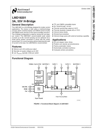
The LMD18201 is a 3 A H‑Bridge driver designed for motion‑control applications such as DC and stepper motor drives, factory‑automation robots and printers. It combines bipolar and CMOS control circuitry with DMOS power devices on a single monolithic structure, delivering up to 3 A continuous and 6 A peak output current.
The datasheet provides absolute maximum ratings, typical performance curves, pinout details, application information, and recommended external components such as bootstrap capacitors and sense resistors for current monitoring.
| Continuous Output Current | 3 A |
|---|---|
| Peak Output Current (200 ms) | 6 A |
| Supply Voltage Range | 12 V to 55 V |
| Thermal Warning Flag Activation Temperature | 145 °C (active‑low) |
| Thermal Shutdown Temperature | 170 °C |
The device can deliver up to 3 A continuous output current.
By adding a small sense resistor (≤0.1 Ω) between the POWER GROUND/SENSE pin (pin 7) and circuit ground.
The thermal flag output goes active‑low when the junction reaches 145 °C.
A 10 nF capacitor is recommended for each bootstrap pin.