
The PC16552D is a dual version of the PC16550D Universal Asynchronous Receiver-Transmitter (UART). The two serial channels are completely independent except for a common CPU interface and crystal input. On power-up, both channels are initially identical to the 16450. Each channel can operate with on-chip transmitter and receiver FIFOs (FIFO mode) to relieve the CPU of excessive software overhead. In FIFO mode, each channel can buffer 16 bytes (plus 3 bits of error data per byte in the RCVR FIFO) of data in both the transmitter and receiver. All the FIFO control logic is on-chip to minimize system overhead and maximize system efficiency. Signalling for DMA transfers is done through two pins per channel (TXRDY and RXRDY). The RXRDY function is multiplexed on one pin with the OUT 2 and BAUDOUT functions. The CPU can select these functions through a new register (Alternate Function Register). Each channel performs serial-to-parallel conversion on data characters received from a peripheral device or a MODEM, and parallel-to-serial conversion on data characters received from the CPU. The CPU can read the complete status of each channel at any time. Status information reported includes the type and condition of the transfer operations being performed by the DUART, as well as any errors.
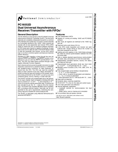
The PC16552D is a dual version of the PC16550D Universal Asynchronous Receiver/Transmitter (UART) providing two completely independent serial channels. Each channel includes on‑chip transmitter and receiver FIFOs, programmable baud‑rate generators, and full modem‑control capabilities.
The document lists absolute maximum ratings, DC and AC electrical characteristics, timing waveforms, register definitions, pin descriptions, a connection diagram, and ordering information, including package dimensions and part numbers.
| FIFO depth per channel | 16 bytes |
|---|---|
| Baud divisor range | 1 to 2^16‑1 |
| Maximum external clock frequency | 24 MHz |
| Package type | 44‑Lead Plastic Chip Carrier (V) |
Each channel has a 16‑byte FIFO buffer.
The device supports an external clock up to 24 MHz.
It is offered in a 44‑Lead Plastic Chip Carrier (V).