
The CAT5259 is four digitally programmable potentiometers (DPPs™) integrated with control logic and 16 bytes of NVRAM memory. Each DPP consists of a series of resistive elements connected between two externally accessible end points. The tap points between each resistive element are connected to the wiper outputs with CMOS switches. A separate 8-bit control register (WCR) independently controls the wiper tap switches for each DPP. Associated with each wiper control register are four 8-bit non-volatile memory data registers (DR) used for storing up to four wiper settings. Writing to the wiper control register or any of the non-volatile data registers automatically loads the wiper settings to the potentiometers, saving switch operation time.
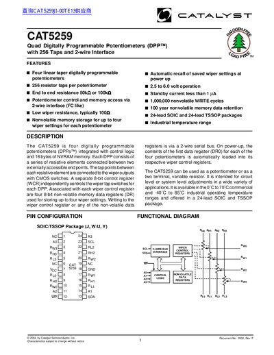
The CAT5259 is a quad digitally programmable potentiometer (DPP) integrating control logic and 16 bytes of non‑volatile memory. Each potentiometer provides 256 resistor taps with selectable end‑to‑end resistance of 50 kΩ or 100 kΩ, and can be used as a variable resistor or a digital potentiometer. Control and memory access are performed via a 2‑wire serial bus similar to I²C.
The datasheet includes pin descriptions, absolute maximum ratings, recommended operating conditions, DC characteristics, timing diagrams, write‑cycle limits, reliability data, and packaging information. It also describes the serial bus protocol, device addressing for up to sixteen devices on the same bus, and write‑protection features.
| Number of potentiometers | 4 |
|---|---|
| Resistor taps per potentiometer | 256 |
| End‑to‑end resistance | 50 kΩ or 100 kΩ |
| Supply voltage range | 2.5 V to 6.0 V |
| Standby current | < 1 µA |
| Operating temperature range | -40 °C to 85 °C |
| Package types | 24‑lead SOIC and 24‑lead TSSOP |
| Non‑volatile write cycles | 1,000,000 cycles |
| Data retention | 100 years |
| Maximum devices on bus | 16 |
It uses a 2‑wire serial bus (I²C‑like) for control and memory access.
Up to sixteen devices can be individually addressed on the bus.
Write protection is enabled by tying the WP pin low, which makes the data registers read‑only.
The standby current is less than 1 µA.