
The MAX195 is a 16-bit successive-approximation analog-to-digital converter (ADC) that combines high speed, high accuracy, low power consumption, and a 10µA shutdown mode. Internal calibration circuitry corrects linearity and offset errors to maintain the full rated performance over the operating temperature range without external adjustments. The capacitive-DAC architecture provides an inherent 85ksps track/hold function. The MAX195, with an external reference (up to +5V), offers a unipolar (0V to VREF) or bipolar (-VREF to VREF) pin-selectable input range. Separate analog and digital supplies minimize digital-noise coupling. The chip select (CS) input controls the three-state serial-data output. The output can be read either during conversion as the bits are determined, or following conversion at up to 5Mbps using the serial clock (SCLK). The end-of-conversion (EOC) output can be used to interrupt a processor, or can be connected directly to the convert input (CONV) for continuous, full-speed conversions. The MAX195 is available in 16-pin DIP, wide SO, and ceramic sidebraze packages.
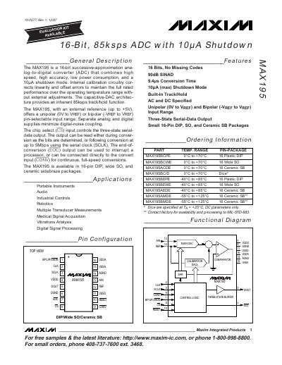
The MAX195 is a 16‑bit successive‑approximation analog‑to‑digital converter (ADC) offering high speed, high accuracy, low power consumption, and a 10 µA shutdown mode. It features an internal capacitive‑DAC architecture that provides an inherent 85 ksps track‑hold function and supports both unipolar (0 V to VREF) and bipolar (‑VREF to VREF) input ranges.
The document includes detailed electrical characteristics, pin configurations, calibration procedures, and timing specifications. It describes the digital interface, external clock requirements, and output data formats, enabling designers to integrate the MAX195 into portable instruments, audio, industrial controls, robotics, and other applications.
| Resolution | 16 bits |
|---|---|
| Maximum Sampling Rate | 85 ksps |
| Shutdown Current | 10 µA (max) |
| Operating Temperature Range | 0 °C to +70 °C |
| Supply Voltage | VDDD = VDDA = +5 V, VSSD = VSSA = -5 V |
| Serial Output Speed | up to 5 Mbps |
| Input Range | Unipolar (0 V to VREF) or Bipolar (‑VREF to VREF) |
The MAX195 can sample at up to 85 ksps.
In shutdown mode the device draws a maximum of 10 µA.
Calibration starts by pulling the RESET pin low and then releasing it high.