
The MAX1112/MAX1113 are low-power, 8-bit, 8-chan- nel analog-to-digital converters (ADCs) that feature an internal track/hold, voltage reference, clock, and serial interface. They operate from a single +4.5V to +5.5V supply and consume only 135µA while sampling at rates up to 50ksps. The MAX1112’s 8 analog inputs and the MAX1113’s 4 analog inputs are software-con- figurable, allowing unipolar/bipolar and single- ended/differential operation. Successive-approximation conversions are performed using either the internal clock or an external serial-inter- face clock. The full-scale analog input range is deter- mined by the 4.096V internal reference, or by an externally applied reference ranging from 1V to VDD. The 4-wire serial interface is compatible with the SPI™, QSPI™, and MICROWIRE™ serial-interface standards. A serial-strobe output provides the end-of-conversion signal for interrupt-driven processors. The MAX1112/MAX1113 have a software-program- mable, 2µA automatic power-down mode to minimize power consumption. Using power-down, the supply current is reduced to 13µA at 1ksps, and only 82µA at 10ksps. Power-down can also be controlled using the SHDN input pin. Accessing the serial interface automat- ically powers up the device. The MAX1112 is available in 20-pin SSOP and DIP packages. The MAX1113 is available in small 16-pin QSOP and DIP packages.
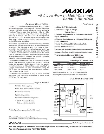
The MAX1112 and MAX1113 are low‑power, 8‑bit analog‑to‑digital converters that operate from a single +4.5 V to +5.5 V supply. They consume only 135 µA while sampling at 50 ksps and can be reduced to 13 µA in power‑down mode. The MAX1112 provides eight analog inputs, while the MAX1113 offers four, both configurable for unipolar/bipolar and single‑ended/differential operation.
A 4‑wire serial interface compatible with SPI™, QSPI™ and MICROWIRE™ provides data transfer and a serial‑strobe output for interrupt‑driven processors. The devices include an internal 4.096 V reference, track‑and‑hold circuitry, and optional external reference. Recommended PCB layout includes a star‑ground for analog signals and careful bypassing of the supply pins.