
This data sheet describes the features of the ADP1877 dual output synchronous buck PWM controller. The controller has an input voltage range of 2.75 V to 14.5 V, an output voltage range of 0.6 V to 90% VIN, a maximum output current of more than 25 A per channel, a programmable frequency of 200 kHz to 1.5 MHz, a Flex-Mode architecture with integrated drivers, a 180° phase shift that minimizes input ripple current and required input capacitance, ±0.85% output voltage accuracy, a temperature range of -40°C to +85°C, integrated boost diodes, a light load pulse skip high efficiency mode, power good with an internal pull-up resistor, overvoltage and overcurrent limit protection, thermal overload protection, input undervoltage lockout (UVLO), externally adjustable soft start, slope compensation and current sense gain, independent precision enable inputs, a synchronization input, and a suitable for any output capacitor 32-lead 5 mm×5 mm package.
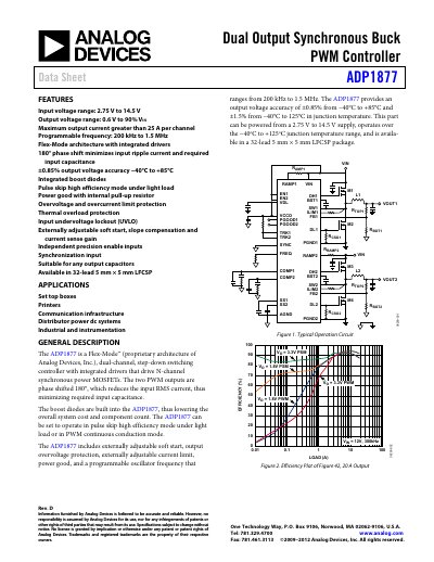
The ADP1877 is a Flex‑Mode™ dual‑channel step‑down switching controller that integrates MOSFET drivers and boost diodes. Its two PWM outputs are phase‑shifted 180°, reducing input RMS current and required input capacitance.
The device operates from 2.75 V to 14.5 V input, delivers up to 25 A per channel, and offers programmable frequency, soft‑start, over‑voltage, over‑current and thermal protection features. It is supplied in a 32‑lead 5 mm × 5 mm LFCSP package and is suited for set‑top boxes, printers, communication infrastructure, and industrial instrumentation. This manual is written in Chinese.
| Input voltage range | 2.75 V to 14.5 V |
|---|---|
| Maximum output current per channel | > 25 A |
| Programmable oscillator frequency | 200 kHz to 1.5 MHz |
| Output voltage accuracy (‑40°C to +85°C) | ±0.85% |
| Output voltage range | 0.6 V to 90% of VIN |
| Operating temperature range (junction) | ‑40°C to +125°C |
The ADP1877 operates from 2.75 V to 14.5 V input voltage.
Each channel can deliver more than 25 A of output current.
The oscillator can be programmed from 200 kHz up to 1.5 MHz.
The device includes over‑voltage, over‑current, thermal shutdown, UVLO, and soft‑start protection.