
The ADP3050 is a high voltage step-down switching regulator with features such as wide input voltage range, adjustable and fixed output options.
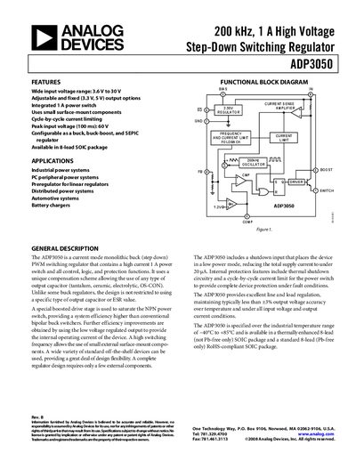
The ADP3050 is a current‑mode monolithic buck (step‑down) PWM switching regulator with a wide input range of 3.6 V to 30 V and an integrated 1 A power switch. It offers adjustable and fixed (3.3 V, 5 V) output options, cycle‑by‑cycle current limiting, and a shutdown mode that reduces supply current to under 20 µA.
The document includes functional block diagrams, pin configurations, typical performance curves, and detailed specifications. It also covers application guidance for industrial power systems, PC peripherals, automotive systems, and battery chargers, along with design notes on inductor and capacitor selection.
| Input Voltage Range | 3.6 V to 30 V |
|---|---|
| Output Voltage Options | Adjustable and fixed (3.3 V, 5 V) |
| Switching Frequency | 170 kHz – 240 kHz |
| Peak Input Voltage (100 ms) | 60 V |
| Integrated Power Switch Current | 1 A |
| Shutdown Quiescent Current | < 20 µA |
The ADP3050 operates from 3.6 V to 30 V input voltage.
It includes thermal shutdown circuitry and a cycle‑by‑cycle current limit for the power switch.
Only a few external components are needed for a complete regulator design.
In shutdown mode the device draws less than 20 µA.