
The ADP1610 is a dc-to-dc step-up switching converter with an integrated 1.2 A, 0.2 Ω power switch capable of providing an output voltage as high as 12 V. With a package height of less than 1.1 mm, the ADP1610 is optimal for space-constrained applications such as portable devices or thin film transistor (TFT) liquid crystal displays (LCDs).
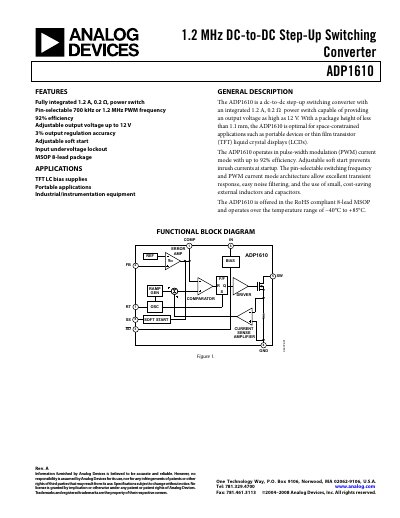
The ADP1610 is a compact step‑up switching converter that integrates a 1.2 A, 0.2 Ω power switch. It operates in current‑mode PWM, offering selectable switching frequencies of 700 kHz or 1.2 MHz, and provides up to 12 V output with 92 % efficiency. The device includes soft‑start, undervoltage lockout, and a shutdown pin for ultra‑low standby current.
Typical applications include TFT‑LCD bias supplies, portable electronics, and other space‑constrained designs. The datasheet details pin functions, layout recommendations, performance curves, and design equations to help engineers select inductors, capacitors, and compensation networks for optimal operation.
| Input Voltage (VIN) | 2.5 V – 5.5 V |
|---|---|
| Output Voltage (VOUT) | Up to 12 V |
| Feedback Voltage (VFB) | 1.212 V – 1.248 V |
| Peak Current Limit (ICLSET) | 2.0 A |
| Operating Temperature Range | −40 °C to +85 °C |
The converter can provide an output voltage as high as 12 V.
Connect the RT pin to IN for 1.2 MHz operation, or connect it to GND for 700 kHz.
Driving SD low turns off the regulator and reduces the input current to about 10 nA.