
ADM1184 is a 0.8% accurate quad voltage monitor produced by Analog Devices. It can monitor 4 power supplies and each power supply can be programmed to monitor different voltage levels using external resistor dividers. ADM1184 has 3 open-drain enable outputs (OUT1, OUT2, and OUT3) and 1 open-drain power-good output (PWRGD), with an internal 190ms delay associated with assertion of PWRGD. ADM1184 is packaged in a 10-lead MSOP.
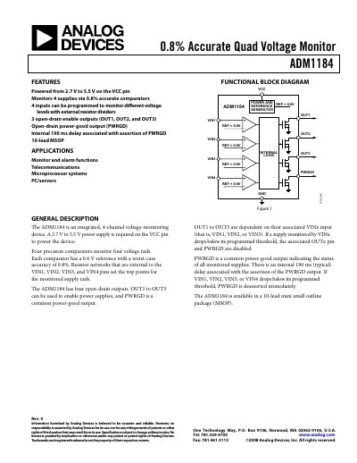
The ADM1184 quad voltage monitor integrates four precision comparators that compare input voltages to a 0.6 V reference with 0.8 % worst‑case accuracy. It operates from a 2.7 V to 5.5 V supply and provides three enable outputs (OUT1‑OUT3) plus a common power‑good output (PWRGD).
Typical applications include power‑up sequencing and monitoring in telecommunications, microprocessor systems, and PC/servers. External resistor dividers set the trip points for each VIN pin, and the device includes internal delays (30 µs propagation, 190 ms PWRGD rise) to ensure stable power‑good signaling.
| Operating Voltage Range (VCC) | 2.7 V to 5.5 V |
|---|---|
| Supply Current (IVCC) typical | 80 µA |
| Input Threshold (VTH) typical | 0.6000 V |
| Output Low Voltage (VOUTL) at VCC=2.7 V | 0.4 V |
| Low‑to‑High Propagation Delay | 30 µs |
| Package Type | 10‑Lead MSOP |
The device operates from 2.7 V to 5.5 V on the VCC pin.
Four open‑drain outputs: OUT1, OUT2, OUT3, and the common power‑good output PWRGD.
The typical delay is about 190 ms after all inputs exceed their thresholds.
Each comparator uses a 0.6 V reference.