
The AKD4393 is an evaluation board for AK4393, which is 96kHz sampling 24Bit ∆Σ DAC. The AKD4393 includes a LPF which can add differential analog outputs from the AK4393 and also has a digital interface with AKM’s wave generator using ROM data and AKM’s ADC evaluation boards. Therefore, it is easy to evaluate the AK4393.
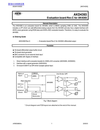
The AKD4393 is an evaluation board for the AK4393 96 kHz 24‑bit audio DAC. It features on‑board differential output buffers, a low‑pass filter, a clock generator, and BNC connectors for external clock input. The board can interface with AKM's A/D converter evaluation boards, signal generators, and includes an on‑board CS8414 optical receiver.
The manual describes power‑supply connections, jumper and DIP‑switch settings for various evaluation modes (DIR optical link, ROM‑generated sine wave, A/D data, or external clock), and provides measurement examples such as THD+N, dynamic range, and S/N ratios at 44.1 kHz and 96 kHz.
| Audio DAC sampling rate | 96 kHz |
|---|---|
| Audio DAC resolution | 24 bit |
| Differential output level (Cannon connector) | 2.94 Vrms (typ @ VREF=5.0 V) |
| Differential output level (BNC connector) | 2 Vrms (typ @ VREF=5.0 V) |
| Digital supply voltage (VP) | 3 V ~ 5.25 V |
| Op‑amp used | NJM5534D |
| THD+N (44.1 kHz) | 102.3 dB |
| THD+N (96 kHz) | 100.9 dB |
Set jumper JP15 (REG) to short for the internal 5 V regulator, or open it to use the external 5 V supply from the A5V jack.
Press SW1 to set the reset line low (L) during power‑up; releasing it (H) releases the reset.
Configure the jumper settings shown in Fig. 3: set JP4, JP1, JP2, JP5, JP7, JP8, JP14, JP9 as indicated for DIR mode.
The Cannon connector provides about 2.94 Vrms (typical at VREF = 5.0 V) and the BNC connector provides about 2 Vrms (typical at VREF = 5.0 V).