
The LMH6514 is a high performance, digitally controlled variable gain amplifier (DVGA). It combines precision gain control with a low noise, ultra-linear, differential amplifier. The LMH6514 drives a high performance ADC in a broad range of mixed signal and digital communication applications such as mobile radio and cellular base stations where auto- matic gain control (AGC) is required to increase system dy- namic range. When used in conjunction with a high speed ADC, system dynamic range can be extended by up to 42 dB. The LMH6514 has a differential input and output allowing large signal swings on a single 5V supply. It is designed to accept signals from RF elements and maintain a terminated impedance environment. The input impedance is 200Ω re- sistive. The output impedance is either 200Ω or 400Ω and is user selectable. A unique internal architecture allows use with both single ended and differential input signals. Input signals to the LMH6514 are scaled by a highly linear, digitally controlled attenuator with seven accurate 6 dB steps. The attenuator output provides the input signal for a high gain, ultra linear differential transconductor. The transconductor differential output current can be converted into a voltage by using the on-chip 200Ω or 400Ω loads. The transconductance gain is 0.1 Amp/Volt resulting in a maximum voltage gain of +32 dB when driving a 200
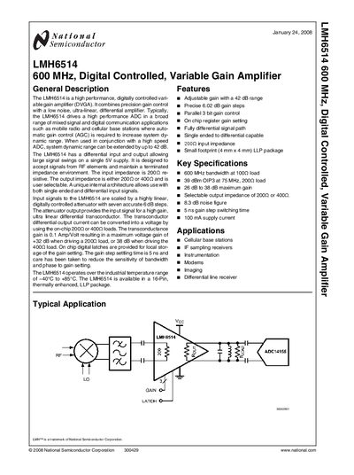
The LMH6514 is a high‑performance, digitally controlled variable gain amplifier (DVGA) designed for mixed‑signal and digital communication applications. It features a fully differential signal path, selectable output impedance, and a small 4 mm × 4 mm LLP package.
The manual details the device’s gain range (up to 42 dB), precise 6.02 dB gain steps, 8.3 dB noise figure, supply voltage range (4 V‑5.25 V), and operating temperature range (‑40 °C to +85 °C). Pin functions, absolute maximum ratings, and typical performance curves are also provided.
| Gain range | 42 dB |
|---|---|
| Gain step size | 6.02 dB |
| Noise figure (max gain) | 8.3 dB |
| Supply voltage (Pin 3) | 4 V to 5.25 V |
| Input impedance | 200 Ω |
Each gain step is 6.02 dB.
The device operates with a supply voltage between 4 V and 5.25 V.
The amplifier provides up to 42 dB of gain.