
This document is about NORITAKE ITRON VFD MODULES GU144x40D-K610A8 Dot Graphic VFD Module. It introduces the features and characteristics of this product.
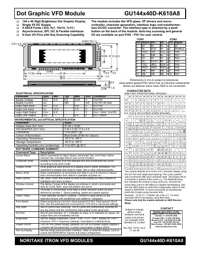
The GU144x40D-K610A8 is a 144 × 40‑dot high‑brightness VFD module that supports four ASCII fonts (5×5, 5×7, 10×14, 7×15) and a proportional mini font, with asynchronous, SPI, I²C and parallel interfaces. It includes a built‑in DC/DC converter, key‑scan I/O pins and a brown‑out detector.
This manual covers hardware dimensions and electrical limits, environmental ratings, how to select and configure the communication interface, the complete set of software commands (cursor movement, character/graphic write, macros, window control, brightness, etc.), and troubleshooting information such as reset timing and packet mode operation.
| Supply Voltage (Vcc) | 4.5 V – 5.25 V |
|---|---|
| Supply Current (Icc) | 380 mA (typical) |
| Logic High Input (V_IH) | 3.0 V – Vcc |
| Logic Low Input (V_IL) | -0.5 V – 1.5 V |
| Logic High Output (V_OH) | 4.2 V (min) |
| Logic Low Output (V_OL) | 0.6 V (max) |
| Display Area | 57.45 mm × 15.85 mm |
| Dot Size / Pitch | 0.25 mm × 0.25 mm (horizontal) / 0.4 mm × 0.4 mm (vertical) |
| Luminance | 1100 cd/m² (typ) |
| Operating Temperature | -40 °C to +85 °C |
| Operating Humidity | 10 % to 90 % (non‑condensing, 25 °C) |
Send the Brightness command (1BH + level) where level = F8H‑FFH; F8H turns the display off, F9H is minimum, FFH is maximum (default).
The factory default interface is the asynchronous serial (SERIAL) mode; the default SPI setting is also provided for synchronous operation.
Apply a low‑level signal to the /RES pin; the module clears the display, restores power‑up defaults, and may take up to 9 ms per stored macro byte for auto‑check.