
This document describes the features and technical specifications of the OCTO series trigger modules, including auto output function, indicators, mechanical design, input circuit, and output circuit.
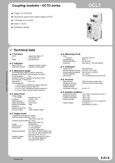
The OCL1 coupling module of the OCTO series offers automatic and manual operation modes, with LED indicators for supply voltage (green) and relay output status (yellow). It features a self‑extinguishing plastic housing with IP40 rating and DIN‑rail mounting according to EN 50022.
Technical data include a maximal switching capacity of 56 VA (2 A / 28 V AC/DC), minimal capacity of 5 VA (1 mA / 5 V AC/DC), contact resistance up to 20 mΩ, and an electrical life of 3 × 10⁴ operations. The module operates from –25 °C to +55 °C, with a supply voltage of 24 V AC/DC and supports various cable terminations.
| Maximal switching capacity | 56 VA (2 A / 28 V AC/DC) |
|---|---|
| Minimal switching capacity | 5 VA (1 mA / 5 V AC/DC) |
| Contact resistance | max. 20 mΩ |
| Electrical life | 3 × 10⁴ operations at maximum load |
| Operating temperature range | -25 °C to +55 °C |
The OCL1 module can switch up to 56 VA (2 A / 28 V AC/DC).
The green LED shows that supply voltage is present, while the yellow LED indicates the state of the relay output.
The housing has an IP40 rating for protection against solid objects.
The module is mounted on a DIN‑rail (TS 35) according to EN 50022.