
The S2 series safety relays are base devices for Emergency Stop and Safety Gate applications. They feature two-channel activation with cross monitoring and synchronous time check. Automatic or manual star activation via semiconductor output (OSSD) is possible. They have 2 enabling current paths and 1 signaling current path. Suitable for applications up to safety category 4. Width is 22.5mm with an industrial design.
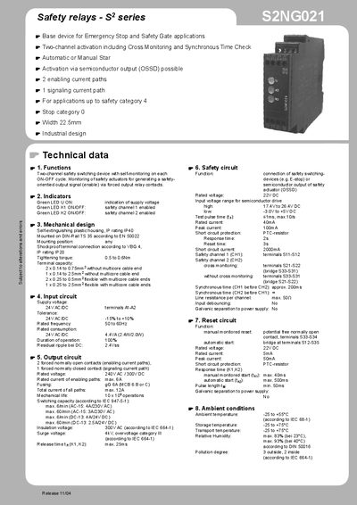
The handbook describes the TELE S2NG021 safety relay, a two‑channel device for emergency‑stop and safety‑gate use. It covers functional modes such as single‑channel, two‑channel, cross‑monitoring, synchronous time check and OSSD compatibility, and explains how the relay reacts to activation, reset and fault conditions.
Technical data, mechanical design, electrical connections, ambient limits and safety circuit parameters are listed, together with wiring diagrams and terminal assignments. The document is intended for system integrators and end‑users who need to install, configure and maintain the relay in industrial automation systems.
| Width | 22.5 mm |
|---|---|
| IP rating (housing) | IP40 |
| IP rating (terminals) | IP20 |
| Supply voltage | 24 V AC/DC |
| Rated frequency | 50 – 60 Hz |
| Rated consumption | 4.4 VA (2.4 W + 2.0 W) |
| Rated voltage (output contacts) | 240 V AC / 300 V DC |
| Enabling‑path current rating | max 6 A |
| Total current rating | max 12 A |
| Mechanical life | 10 × 10° operations |
| Ambient temperature range | -25 °C to +55 °C |
It operates from a 24 V AC or DC supply applied to terminals A1‑A2.
The enabling current paths are rated for a maximum of 6 A.
Yes, it is suitable for applications up to safety category 4.