
The Vaisala PDT101 differential pressure transmitter is a high-performance instrument primarily designed for life science and cleanroom applications. It features a measurement range of ±60 Pa or ±0.25 in. w.c., an accuracy of 0.4 % full scale, and a long-term stability of ≤0.5 % full scale/year. The PDT101 can be installed on an EN550022 rail or by using M4 (0.7) bolts and nuts through the tapped mounting holes.
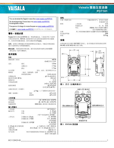
This guide introduces the Vaisala PDT101 differential pressure transmitter, a high‑performance instrument designed for life‑science and clean‑room applications. It covers safety warnings, technical specifications, and recommended installation methods.
The document explains how to adjust zero offset, connect current or voltage output wiring, perform routine maintenance, and locate warranty information. It also includes diagrams of the device, wiring layouts, and mechanical dimensions.
| Measurement range | +60 Pa (±0.25 in H₂O) |
|---|---|
| Overload pressure | 1.7 bar |
| Static pressure rating | 1.7 bar |
| Long‑term stability | < 0.5 % FS/year |
| Preheat time | 15 s |
| Operating temperature | -18 °C to +70 °C |
| Storage temperature | -40 °C to +82 °C |
| Current output | 4–20 mA (2‑wire) |
| Voltage output (standard) | 0.5 VDC (3‑wire) |
Use the zero‑adjustment potentiometer on the front left side of the instrument with a flat‑head or Phillips screwdriver to reduce any zero‑offset up to about +1 % when mounted horizontally.
Connect the left‑side negative (‑) terminal and the right‑side positive (+) terminal; link the power positive to the PDT101 positive terminal, the power negative to the BCS 4‑20 mA input negative, and the PDT101 negative terminal to the BCS input positive.