
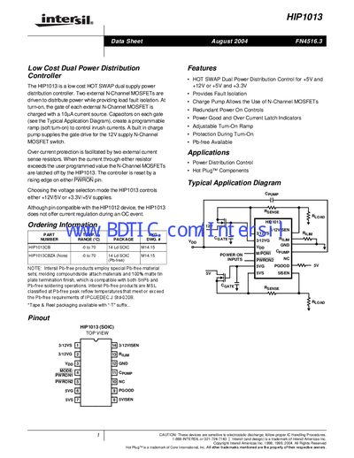
The HIP1013 is a low cost HOT SWAP dual supply power distribution controller. Two external N-Channel MOSFETs are driven to distribute power while providing load fault isolation. At turn-on, the gate of each external N-Channel MOSFET is charged with a 10µA current source. Capacitors on each gate (see the Typical Application Diagram), create a programmable ramp (soft turn-on) to control inrush currents. A built in charge pump supplies the gate drive for the 12V supply N-Channel MOSFET switch. Over current protection is facilitated by two external current sense resistors. When the current through either resistor exceeds the user programmed value the N-Channel MOSFETs are latched off by the HIP1013. The controller is reset by a rising edge on either PWRON pin. Choosing the voltage selection mode the HIP1013 controls either +12V/5V or +3.3V/+5V supplies. Although pin compatible with the HIP1012 device, the HIP1013 does not offer current regulation during an OC event.
The HIP1013 controller provides hot‑swap dual power distribution for either +12 V/5 V or +3.3 V/5 V supplies. It drives two external N‑Channel MOSFETs, includes a charge pump for the 12 V gate drive, and offers over‑current protection via external sense resistors.
The device is supplied in a 14‑lead SOIC package (HIP1013CB or HIP1013CBZA Pb‑free) and operates from a 10.5 V to 16 V Vpp supply over a temperature range of –40 °C to 85 °C. Detailed electrical specifications, pin descriptions, and typical performance curves are provided.
| Maximum Junction Temperature | 150 °C |
|---|---|
| Charge Pump Output Voltage (No load) | ≈17.4 V |
It can control either a +12 V/5 V pair or a +3.3 V/5 V pair of supplies.
Two external current‑sense resistors monitor load current; when the sensed voltage exceeds a programmed threshold, the controller latches off both MOSFETs.