
The SL34118 Voice Switched Speakerphone Circuit incorporates the necessary amplifiers, attenuators, level detectors, and control algorithm to form the heart of a high quality hands-free speakerphone system.
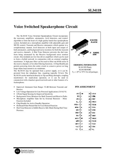
The SL34118 integrates amplifiers, attenuators, level detectors and control logic to enable a high‑quality hands‑free speakerphone. It supports line‑powered operation (5 mA typical) or external supply, and provides features such as microphone gain control, mute, chip‑disable, dial‑tone detection and background‑noise monitoring.
The document details the functional blocks (filter, hybrid amplifiers, microphone amplifier, attenuator control), pin descriptions, electrical characteristics and operation modes (transmit, receive, fast idle, slow idle). Designers can configure gain, thresholds and timing via external components and resistors.
| Supply voltage range | 2.8 V to 6.5 V |
|---|---|
| Typical supply current | ≈5.0 mA |
| Input impedance (TXI/RXI) | ≈10 kΩ |
| Maximum input signal level | 350 mVrms |
| Output impedance (amplifier outputs) | <10 Ω |
| Chip Disable pin threshold | ~1.5 V |
| Volume control bias current | ≈60 nA |
| Microphone amplifier open‑loop gain | ≈80 dB |
The device works with a supply voltage from 2.8 V up to 6.5 V.
Applying a logic high (>2.0 V) to the MUT pin (Pin 12) reduces the microphone amplifier gain by about –39 dB, effectively muting the circuit.
When the CD pin is driven high (>2.0 V) the IC powers down, disabling the microphone, hybrid amplifiers and attenuators to conserve power.