
Key facts
- Manuals
- 13
- Languages
- EN
- Last added
- 2012-08-06
Featured SLS manuals
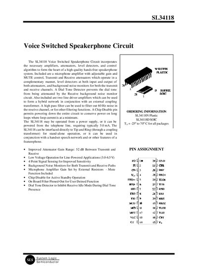
System Logic SL34118 Voice Switched Speakerphone Circuit Manual
The SL34118 integrates amplifiers, attenuators, level detectors and control logic to enable a high‑quality hands‑free speakerphone. It supports line‑powered operation (5 mA typical) or external supply, and provides features such as microphone gain control, mute, chip‑disable, dial‑tone detection and background‑noise monitoring.
The document details the functional blocks (filter, hybrid amplifiers, microphone amplifier, attenuator control), pin descriptions, electrical characteristics and operation modes (transmit, receive, fast idle, slow idle). Designers can configure gain, thresholds and timing via external components and resistors.
Covers: Simplified Block Diagram · Functional Description · Attenuators · Level Detectors · Background Noise Monitors · Volume Control
Latest SLS manuals
SLS SL74HC4094 handbook
SLS SL74HC4053 handbook
SL74HC4053 is a high-performance silicon-gate CMOS analog multiplexer/demultiplexer produced by System Logic Semiconductor SLS. It features fast propagation delays, low on-resistances, and low off-leakage currents. The analog multiplexers/demultiplexers control analog voltages that may vary across the complete power supply range (from VCC to VEE). The Channel-Select inputs determine which one of the Analog Inputs/Outputs is to be connected, by means of an analog switch, to the Common Output/Input. When the Enable pin is high, all analog switches are turned off. The Channel-Select and Enable inputs are compatible with standard CMOS outputs; with pullup resistors, they are compatible with LS/ALSTTL outputs.
SLS SL74HC4052 handbook
The SL74HC4052 is a high-performance silicon-gate CMOS analog multiplexer/demultiplexer from System Logic Semiconductor SLS. It achieves fast propagation delays, low ON resistances, and low OFF leakage currents. This product controls analog voltages that may vary across the complete power supply range (from VCC to VEE). The Channel-Select inputs determine which one of the Analog Inputs/Outputs is to be connected, by means of an analog switch, to the Common Output/Input. When the Enable pin is high, all analog switches are turned off. The Channel-Select and Enable inputs are compatible with standard CMOS outputs; with pullup resistors, they are compatible with LS/ALS TTLoutputs.
SLS SL74HC4046 handbook
SLS SL4518B DATA SHEET
SLS SL4012B handbook
The SL4012B is a high-voltage silicon-gate CMOS dual 4-input NAND gate produced by System Logic Semiconductor SLS. The operating voltage range is 3.0 to 18 V, the maximum input current is 1 µA, and the noise margin is 1.0 V min @ 5.0 V, 2.0 V min @ 10.0 V, and 2.5 V min @ 15.0 V.
SLS SL74HCT240 DATA SHEET
The SL74HCT240 is a high-performance octal 3-state inverting buffer/line driver/line receiver that can be used as a level converter for interfacing TTL or NMOS outputs to High Speed CMOS inputs. It features inverting outputs and two active-low output enables.
SLS SL74HC4015 Dual 4-Bit Shift Register
The SL74HC4015 is a high-performance silicon-gate CMOS dual 4-bit shift register. The device inputs are compatible with standard CMOS outputs; with pullup resistors, they are compatible with LS/ALSTTL outputs. This device consists of two identical independent 4-stage serial-input/parallel-output registers. Each register has independent Clock and Reset inputs as well as a single serial Data input. “Q” outputs are available from each of the four stages on both registers. All register stages are D-type, master-slave flip-flops. The logic level present at the Data input is transferred into the first register stage and shifted over one stage at each positive-going clock transition. Resetting of all stages is accomplished by a high level on the reset line.
SLS SL74HCT132 Quad 2-Input NAND Gate with Schmitt-Trigger Inputs
The SL74HCT132 is a high-performance silicon gate CMOS chip with four 2-input NAND gates and Schmitt-trigger inputs. It can be used as a level converter for interfacing TTL or NMOS outputs to high-speed CMOS inputs.
SLS SL74HC393 handbook
The SL74HC393 is a dual 4-bit binary ripple counter with parallel outputs from each counter stage. Its outputs directly interface to CMOS, NMOS, and TTL, with an operating voltage range of 2.0 to 6.0V and a low input current of 1.0µA. It also has the high noise immunity characteristic of CMOS devices.
SLS SL74HC367 DATA SHEET
The SL74HC367 is a high-performance hex 3-state noninverting buffer with separate 2-bit and 4-bit sections. It has outputs that directly interface to CMOS, NMOS, and TTL, with an operating voltage range of 2.0 to 6.0V. It has low input current and high noise immunity characteristic of CMOS devices.
SLS SL74HC374 handbook
The SL74HC374 is a high-performance silicon-gate CMOS octal 3-state noninverting D flip-flop. It has the same pinout as the LS/ALS374. The device inputs are compatible with standard CMOS outputs, and with pull-up resistors, they are compatible with LS/ALSTTL outputs. Data meeting the setup and hold time is clocked to the outputs with the rising edge of the Clock. The Output Enable input does not affect the states of the flip-flops, but when Output Enable is high, the outputs are forced to the high-impedance state; thus, data may be stored even when the outputs are not enabled.
System Logic SL34118 Voice Switched Speakerphone Circuit Manual
Application Note 12 pages · 140 KB · ENTechnical description of the SL34118 voice‑switched speakerphone IC, including functional blocks, pinout and key specifications.
Which document do I need?
Application Note
How to use the product for one specific task, with worked examples.
Questions answered in SLS manuals
What supply voltage range does the SL34118 operate from?
The device works with a supply voltage from 2.8 V up to 6.5 V.
From: System Logic SL34118 Voice Switched Speakerphone Circuit Manual
How is the mute function activated on the SL34118?
Applying a logic high (>2.0 V) to the MUT pin (Pin 12) reduces the microphone amplifier gain by about –39 dB, effectively muting the circuit.
From: System Logic SL34118 Voice Switched Speakerphone Circuit Manual