
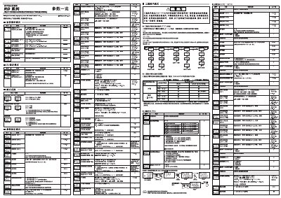
The document describes the functions and configuration of the RD series digital temperature controllers, including engineering‑technology mode, event settings, and PID control. It explains how to monitor input values, set output limits, and use the AUTO and MAN modes.
Detailed instructions cover input range selection, current detector configuration, timing functions, lock levels, and safety interlock settings. Users are guided on how to adjust parameters such as temperature set‑points, proportion‑integral‑derivative limits, and event‑driven actions. This manual is written in Chinese.
| Input monitoring range | 0.0–100.0 A (CTL‑12‑S56‑10L‑N) |
|---|---|
| Current detector CT2 range | 0.0–30.0 A (CTL‑6‑P‑N) |
| PID output limit range | -5.0 % to 105.0 % |
The controller displays input values in the range 0.0–100.0 A using the input monitoring function.
When the controller is in AUTO mode, the indicator lamp lights to show automatic operation.
Set the lower and upper PID output limits, for example –5.0 % as the lower limit and 105.0 % as the upper limit.