
This instruction manual introduces the use of MG10-P1/MG10-P2 multi-interface unit/main module, and provides detailed descriptions of the product's basic functions, installation methods, operating methods, maintenance methods and safety precautions.
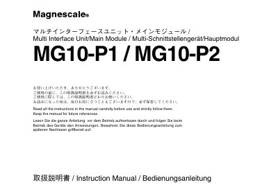
This manual covers safety precautions, regulatory compliance (FCC Class A, CE, EN standards) and warranty information for the Magnescale MG10‑P1/P2 multi‑interface units. It explains the product’s modular architecture, including the main module, optional counter modules, I/F modules and BCD modules, and describes how to configure and link up to 16 units for a total of 64 channels.
Detailed sections provide wiring diagrams, RS‑232C interface specifications, DIN‑rail mounting instructions, connector pin assignments, and command lists for setup and operation. The document also outlines the device’s input resolution options, power requirements, and the non‑explosion‑proof nature of the hardware. This manual is written in Japanese.
| Input resolution | 0.1 nm, 0.5 µm, 1 µm, 5 µm, 10 nm |
|---|---|
| Maximum total channels | 64 channels (via linking up to 16 units) |
| Power input | DC 12 V – 24 V |
| Mounting | 35 mm DIN rail |
| Communication interface | Standard RS‑232C |
| Maximum cable length (signal) | 30 m (10 m if shared with power) |
| Explosion‑proof rating | Not explosion‑proof; not for flammable gas atmospheres |
The device operates on DC power; AC must never be connected.
No, the units are not explosion‑proof and must not be used where flammable gases are present.
Signal and power cables may be up to 30 m long, or 10 m if the same cable carries both.
Up to 16 units can be linked, allowing a total of 64 counter modules.