
This document is an AD5560 device power circuit note, which introduces the function and advantages of the circuit, and gives detailed design principles and application examples
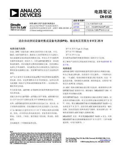
This document provides detailed circuit notes for designing a device‑power‑supply (DPS) using the AD5560. It explains the required external components such as reference voltage sources, ADCs, temperature monitors, and compensation capacitors, and describes how to configure output voltage and current ranges for various test‑equipment applications.
The notes also cover practical design considerations like capacitive load handling, layout and grounding recommendations, and optional diode or MOSFET solutions for high‑current output stages. Revision history and further reading references are included. This manual is written in Chinese.
| Output voltage range | 0 V to 25 V |
|---|---|
| Maximum output current | up to 1.2 A (limited to low‑voltage rails) |
| Allowed AVDD‑AVSS voltage span | < 33 V |
| Number of on‑chip temperature monitoring diodes | 16 |
The AD5560 can provide an output voltage from 0 V up to 25 V, with additional lower‑range options such as 0 V‑7 V and 0 V‑3 V depending on the offset DAC setting.
It can deliver up to 1.2 A, but this current is only available for low‑voltage rails (≤ 3.5 V).
The device contains an array of 16 temperature‑monitoring diodes located at different points on the chip.