
This is the installation instruction of EMV-APP01 multi-function I/O extension card
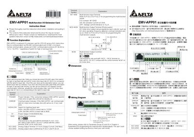
This instruction sheet explains how to install and use the EMV-APP01 multi‑function I/O extension card with Delta VFD‑VE series AC motor drives. It covers communication setup via the RS‑485 port, baud‑rate switching, and the meaning of the status LEDs.
The document details each terminal on the card, including power output (5 V DC/500 mA max), analog output (0‑10 V, 2 mA max), and multi‑function input/output pins. Wiring diagrams and parameter references are provided for configuring the card to match the drive settings. This manual is written in Chinese.
| High baud rate | 115200 |
|---|---|
| Low baud rate | 9600 |
| Power output | 5 VDC / 500 mA max |
| Analog output voltage range | 0 V – 10 V (2 mA max) |
| MCM common output max | 48 VDC / 50 mA |
| POWER LED status | Steady on when connection is correct |
First disconnect the RS‑485 cable, then change the high/low baud‑rate switch and set the AC motor drive baud rate to match the switch setting.
The POWER LED stays steadily on when the EMV‑APP01 card is correctly connected to the AC motor drive.
The analog output can supply up to 2 mA max.