
Key facts
- Brand
- NKK SWITCHES
- Model
- LCD 36x24 Logic Boards
- Documents
- 2
- Languages
- EN
- Last added
- 2023-10-21
Start here
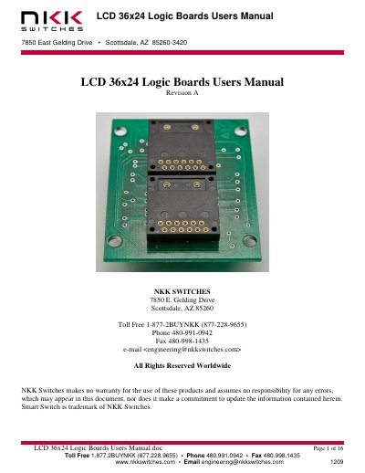
NKK Switches LCD 36x24 Logic Boards User Manual
This user manual describes the LCD 36x24 logic boards made by NKK Switches, used for mounting SmartSwitches or SmartDisplays. It covers features like daisy-chaining via ribbon cables, part number configurations, and board dimensions. The boards support various switch types including pushbutton and display variants, with options for direct mounting or socketed installation.
Read onlineNKK Switches LCD 36x24 Logic Boards specifications
| Logic Board Type | 4-bit logic (except IS-LO102-ISISABCP4CF which is 2-bit) |
|---|---|
| Voltage Options | Standard 9 to 12 V or 5 V |
| Socket Options | No socket or soldered sockets for IS switches |
All NKK Switches LCD 36x24 Logic Boards documents by type
Day-to-day operation, settings and troubleshooting. Start here if the product is already set up.
Questions answered in these manuals
What are the different types of LCD 36x24 logic boards?
There are four types: Bicolor/Monocolor pushbutton, RGB pushbutton, Bicolor/Monocolor/RGB display, and Bicolor/Monocolor/RGB compact.
How are the logic boards connected in a daisy chain?
The controller connects to J1 of the first board via a 14-pin ribbon cable. J2 of the first board connects to J1 of the next board, and so on.
What are the different types of LCD 36x24 logic boards?
There are four types: Bicolor/Monocolor pushbutton, RGB pushbutton, Bicolor/Monocolor/RGB display, and Bicolor/Monocolor/RGB compact.
How are the logic boards connected in a daisy chain?
The controller connects to J1 of the first board via a 14-pin ribbon cable; J2 of the first board connects to J1 of the next board, and so on.