
Key facts
- Brand
- NKK SWITCHES
- Model
- LCD 64x32 Logic Boards
- Documents
- 2
- Languages
- EN
- Last added
- 2023-10-21
Start here
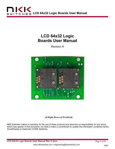
NKK Switches LCD 64x32 Logic Boards User Manual
This document provides detailed instructions for using NKK Switches' LCD 64x32 Logic Boards. It covers how to connect and control the boards via daisy-chaining, pin configurations, switch numbering, and scan protocols. The manual also includes board dimensions, schematics, and key terms for communication formats. It is intended for users integrating these boards with controllers or microcontrollers.
Read onlineNKK Switches LCD 64x32 Logic Boards specifications
| Logic Board Dimensions | Varies by model (L02A1, L02G1, L02H2, L04G2) |
|---|---|
| Connector Type | 7x2 male header with 0.1” x 0.1” spacing |
| Power Supply | 7V to 12V |
| Switch Scan Interval | More than 10ms apart, less than 80ms |
All NKK Switches LCD 64x32 Logic Boards documents by type
Day-to-day operation, settings and troubleshooting. Start here if the product is already set up.
Questions answered in these manuals
What is the power supply range for the logic boards?
7V to 12V, with 7V being preferred.
How are switches numbered on the logic boards?
Switches are numbered row by row, starting with switch one in the upper left corner of the first board, then continuing sequentially across boards.
What are the three types of LCD 64x32 logic boards?
The three types are RGB pushbutton, RGB display, and RGB compact.
How are logic boards connected in a daisy chain?
The J2 of the first logic board connects to J1 of the second logic board, and so on.