
Vishay Siliconix SiC437/SiC438 reference board manual for the 3 V to 24 V synchronous buck regulator, including jumpers, test points, and configurations.
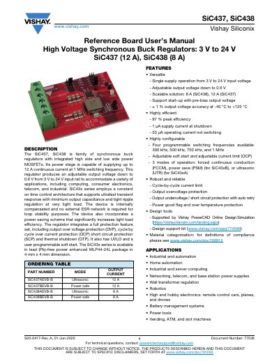
The document is the Reference Board User's Manual for the Vishay Siliconix SiC437 and SiC438 high voltage synchronous buck regulators. The SiC43x family integrates high-side and low-side power MOSFETs, supplies up to 12 A continuous current at 1 MHz switching frequency, and provides an adjustable output voltage down to 0.6 V from a 3 V to 24 V input rail.
The manual describes the evaluation board power terminals, signal and test points, enable jumper J9, output-voltage jumper J15, Mode 1 jumpers J1–J4 for switching frequency and operating mode, and Mode 2 jumpers J5–J8 for soft-start and OCP settings. It also lists typical predefined operating configurations for the SiC437 EVB and SiC438 EVB and covers the PVIN enhanced UVLO option and power-up procedure.
| Input voltage range | 3 V to 24 V |
|---|---|
| Output voltage | Adjustable down to 0.6 V |
| Continuous output current | Up to 12 A |
| Output current by model | SiC438: 8 A; SiC437: 12 A |
| Programmable switching frequencies | 300 kHz, 500 kHz, 750 kHz, 1 MHz |
| Peak efficiency | 97% |
| Output voltage accuracy | ±1% at -40 °C to +125 °C |
| Shutdown supply current | 1 μA |
| Operating current, not switching | 50 μA |
| Package | MLP44-24L, 4 mm x 4 mm, lead (Pb)-free |
The regulators support single-supply operation from 3 V to 24 V input voltage.
The power stage can supply up to 12 A continuous current at 1 MHz switching frequency.
With the two pins of J9 left open, the device is enabled; with the two pins shorted, it is disabled.
The default setup is 5.0 V.