
This manual explains hardware connections, interface definitions, power options, adapter boards, driver installation, and serial communication testing for…
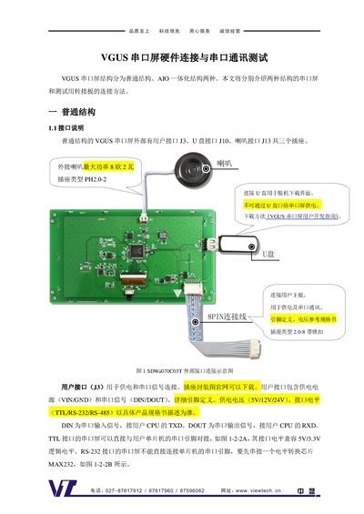
The guide covers two hardware structures of VGUS serial screens: the normal structure with separate user connectors (J3, J10, J13) and the AIO integrated structure that uses a single 10‑pin FPC connector. Detailed pin definitions, supported voltage levels (TTL, RS‑232, RS‑485) and power requirements (5 V/12 V/24 V for normal, 5 V for SDWa AIO, 3.3 V for SDWn AIO) are provided.
Adapter boards (DLB07, AIO01, AIO03, AIO035) simplify connections to a host board, USB, speakers, USB drives and TF cards. The DLB07 board includes a CP2102 USB‑to‑UART bridge and driver installation instructions. The manual also describes step‑by‑step serial communication testing using register read commands and the VGUS development tool. This manual is written in Chinese.
| Normal structure supply voltage | 5 V / 12 V / 24 V |
|---|---|
| Interface voltage levels | TTL / RS‑232 / RS‑485 |
| SDWa AIO series supply voltage | 5 V |
| SDWn AIO series supply voltage | 3.3 V |
| Default baud rate | 115200 |
Send the read‑register command A5 5A 03 81 00 01 to register 0x00; a correct response A5 5A 04 81 00 01 43 indicates the communication is functional.
Small (≤5‑inch) screens can be powered directly from a computer USB port, while larger screens require external power (5 V, 12 V or 24 V) connected to the J3 connector.