
Servo Debugging Software Function Usage Instructions

This manual provides usage instructions for a servo debugging software, covering connection, driver information, IO configuration, fault monitoring…
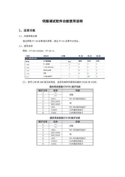

Servo Debugging Software Function Usage Instructions - cover page
Brand
Unknown
Document type
User Manual
Language
Chinese
Pages
9
File format
PDF
File size
789 KB
Published
14 October, 2026
Updated
14 October, 2026
MD5 checksum
A26B3874C9717ACB214F1035434BDBD8

About this manual

This document serves as a user guide for a servo debugging software tool. It details the procedures for establishing communication between a computer and a servo driver via USB to RS485 adapters, including specific wiring instructions for the DB9 connector. The software allows users to view driver information such as DSP and FPGA versions, and monitor digital and analog IO states. This manual is written in Chinese.

What's inside

  • Connection Function
  • Driver Information
  • Digital IO Configuration
  • Analog IO Monitoring
  • Fault Monitoring
  • Parameter Tuning
  • Driver Status Monitoring
  • Debug Functions
  • Oscilloscope Function
  • Parameter Settings

Frequently asked questions

How do I connect the computer to the servo driver using a USB-to-485 cable?

Connect the cable's pin 1 (485+) and pin 2 (485-) to DB9 pins 3 and 6, respectively, while connecting pin 5 (GND) to DB9 pin 5.

What is the maximum number of data points that can be collected in single acquisition mode?

The software can collect a maximum of 1000 data points before reading and displaying the waveform.

Which communication protocol does the debugging software currently support?

The software only supports communication protocol 6, which is identified as RTU in section 7.N.2.

Download PDF (789 KB)

More Unknown Manuals


View all Unknown manuals →