
The Sundray NAP-2800 wireless access point installation guide provides step‑by‑step instructions, safety notes, and mounting details for indoor ceiling…
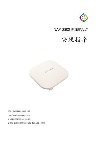
This guide introduces the NAP-2800 indoor wireless access point, its physical features, and technical specifications. It covers safety precautions, environmental requirements, and the tools and materials needed for a successful installation.
Detailed installation procedures are provided for ceiling, wall, and desktop mounting, including wiring, power options (PoE or local 12 V), and post‑installation checks such as status‑LED indications and network connectivity. This manual is written in Chinese.
| Model | NAP-2800 |
|---|---|
| Weight | 0.4 kg |
| Dimensions (W×L×H) | 196 mm × 196 mm × 45 mm |
| Ethernet Port | 1×10/100/1000 Mbps PoE |
| PoE Standard | 802.3af/802.3at |
| Local Power Input | 12 V / 1.5 A |
| Antenna | Built‑in matrix smart antenna |
| MTBF | > 250 000 h |
| Transmit Power | ≤ 20 dBm |
| Maximum Data Rate (2.4 GHz) | 300 Mbps |
| Maximum Data Rate (5 GHz) | 300 Mbps |
| Operating Frequency Bands | 5.725‑5.850 GHz (5 GHz) and 2.4‑2.483 GHz (2.4 GHz) |
The device can be powered either by PoE (compatible with 802.3af/802.3at) or by a local 12 V / 1.5 A power supply.
It is an indoor‑only device and can be mounted on the ceiling, wall, or placed on a desktop, provided the location is dry, ventilated, and free from strong RF interference.
The LED blink codes correspond to specific alarm reasons such as IP acquisition failure, gateway issues, controller communication problems, or tunnel establishment failures, as listed in the alarm table.