
This guide details the installation and removal procedures for Sumitomo Taper-Grip® bushings used with Speed reducers and gearmotors.
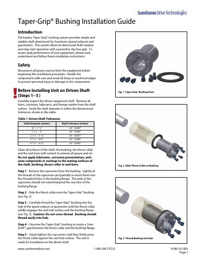
The Taper-Grip® bushing system provides a keyless, reliable shaft attachment for Sumitomo Speed reducers and gearmotors, allowing for bi-directional rotation and stop-start operation. Before installation, users must inspect the driven shaft for burrs or corrosion and verify that the shaft diameter falls within the specified dimensional tolerances listed in Table 1. Mating surfaces must be clean and free of lubricants or coatings.
| Shaft Diameter Tolerance (3/4" - 1 1/8") | +0" –0.005" |
|---|---|
| Shaft Diameter Tolerance (1 3/16" – 2") | +0” –0.006" |
| Capscrew Torque (Model 107C) | 50 Nm (37 Lb.Ft.) |
| Capscrew Torque (Model 215G) | 250 Nm (185 Lb.Ft.) |
It provides simple and reliable shaft attachment for Sumitomo Speed reducers and gearmotors.
Yes, the system allows bi-directional shaft rotation and stop-start operation with a powerful, slip-free grip.
All surfaces of the shaft, bushing, thrust collar, and unit bore must be cleaned with solvent to remove grease and oil.