
Installation manual for the NorthStar SLIM Tach ST1250 bearingless encoder: specifications, electrical connections, wiring and mechanical installation.
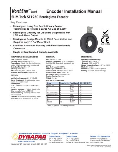
Installation manual for the NorthStar brand SLIM Tach ST1250 bearingless encoder from Dynapar. The document lists key features and standard operating characteristics, including an incremental magnetic code with 64-2048 PPR, single or dual isolated outputs, and a bearingless design that mounts to 250-C face motors and requires only 1.1” of motor shaft.
It then gives electrical connection details, wiring and grounding guidelines, the meaning of the built-in multicolor LED status light, answers to frequently asked questions, and step-by-step mechanical installation instructions with tightening torques for the housing, wheel and cover.
| Pulses per Revolution | 64-2048 PPR |
|---|---|
| Input Voltage Requirement | 5-26 Volts DC |
| Current Requirement | 95 mA typical per sensor module plus line driver load |
| Output Signals | IC-WE Differential Line Driver: 150mA, sink or source |
| Frequency Response | 0 - 180kHz |
| Connector | 10 pin industrial duty latching, sealed NEMA 4 &12, IP65; MS connector or pig-tail |
| Bore Size | 5/8” to 3-3/4” |
| Mounting Configuration | 12.5” C-Face Mount for NEMA MG1-4 standards |
| Max. Shaft Speed | 7,000 RPM |
| Operating Temperature Range | Standard: -40°C to +100°C; Extended: -40°C to +120°C |
| Housing Material | Aluminum |
| Weight | 11.0 lbs. |
| Shock | 300 G’s Min. |
| Humidity | Up to 98% (non-condensing) |
Do not connect them to the receiving device. Any unused encoder signal wires must be individually insulated and tied back, and they should never be in contact with common, power sources or other output signal lines.
The output signal connections must be switched. If the encoder has a single ended output, swap A and B; if it has a differential line driver, swap A and –A.
It shows the overall condition of the encoder: off means no power, low supply voltage below 3.0 VDC or total failure; green means correct power and ready to operate; flashing means the unit is operating and sending pulses; flashing red means low power below 4.5 VDC or a line driver failure.
For European-based applications requiring CE compliance, cable length must not exceed 30 m.