
Quick installation guide for the MRC Systems Compact 4-axis laser beam stabilisation system, covering setup, connections, adjustment, and operation.
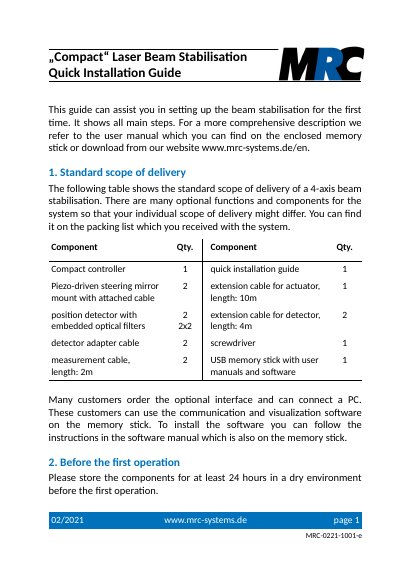
MRC Systems Compact is a 4-axis laser beam stabilisation system with two independent control stages, each with a Piezo-driven actuator and a position detector. This quick installation guide covers first-time setup, including component placement, cable connections, power-on, detector intensity adjustment, beam pre-adjustment, direction coding, fine-adjustment, full operation, accuracy determination, and optional bandwidth optimization.
It also lists the standard scope of delivery and states that components should be stored in a dry environment for at least 24 hours before first operation. For more comprehensive instructions, the guide refers to the user manual available on the enclosed memory stick or for download from the manufacturer's website.
| Axes | 4 |
|---|---|
| Control stages | 2 independent |
| Power input | 12 V |
| Recommended mirror-to-detector distance | 0.5 m or more |
| Position output voltage (typical good values) | 10-100 mV |
| Actuator extension cable length | 10 m |
| Detector extension cable length | 4 m |
| Measurement cable length | 2 m |
They should be stored for at least 24 hours in a dry environment.
A distance of 0.5 m or more is recommended.
Toggle the corresponding Directions switch x or y at the controller.
Use the potentiometer at the detector housing; turning it counter-clockwise increases the gain.