
Microchip dsPICDEM MC1 Motor Control Development Board User Guide

This guide explains how to set up the dsPICDEM MC1 development board, connect motors, and run motor control demos using software modes.
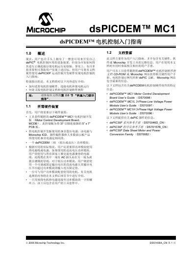

Microchip dsPICDEM MC1 Motor Control Development Board User Guide - cover page
Brand
MICROCHIP
Category
Other Electronics
Document type
User Manual
Language
Chinese
Pages
10
File format
PDF
File size
307 KB
Published
16 October, 2026
Updated
16 October, 2026
Model
MC1
MD5 checksum
BC6041BB68B26915FF2878ADB5F061E7

About this manual

This document serves as an introduction to using the dsPICDEM™ MC1 Motor Control Development Board (MCDB) to develop motor control applications. It covers the necessary hardware components, including the MCDB, power modules, and motors, and explains how to connect them to operate the system. The guide details the setup process for both high-voltage and low-voltage power modules. This manual is written in Chinese.

What's inside

  • Overview
  • Quick Start Demo Guide
  • Software Mode Selection
  • Button and Potentiometer Functions
  • Motor Types
  • Hardware Setup
  • Three-Phase ACIM Connection
  • Split-Phase ACIM Connection

Specifications

MCDB Dimensions5" x 7" PCB

Frequently asked questions

What is the physical size of the dsPICDEM MC1 motor control development board?

The control board is a 5-inch by 7-inch PCB with a 37-pin connector.

What voltage range is required for a three-phase AC induction motor used with the high voltage power module?

The motor must have a rated operating voltage of 110-230 VAC.

What is the maximum power rating for a motor used with the low voltage power module?

The low voltage power module is designed to drive motors rated at 400W or less.

What is the maximum input voltage supported by the low voltage power module?

The low voltage power module supports drive voltages up to a maximum of 48V.

Download PDF (307 KB)

More MICROCHIP Manuals


View all MICROCHIP manuals →