
Reference manual for Microchip dsPIC33F family microcontrollers covering CPU architecture, registers, instruction set, and DSP features.
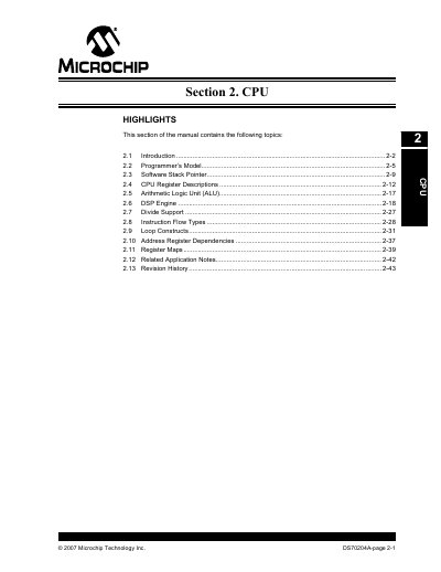
The dsPIC33F Family Reference Manual provides a detailed description of the CPU core, programmer's model, and instruction set for the dsPIC33F microcontroller family. It outlines the 16‑bit data Harvard architecture, 24‑bit instruction word, and the integrated digital signal processing engine.
Key sections include CPU highlights, register maps, DSP engine specifications, stack pointer operation, shadow registers, and related application notes. The document also lists revision history and provides guidance for developers implementing code on these devices.
| Data bus width | 16‑bit |
|---|---|
| Instruction word width | 24‑bit |
| Program counter width | 24‑bit |
| Maximum program memory | 4M × 24 bits |
| Working registers | 16 × 16‑bit |
| DSP multiplier size | 17‑bit × 17‑bit |
| ALU width | 40‑bit |
| Accumulator width | 40‑bit (two accumulators) |
| Barrel shifter width | 40‑bit |
| Interrupt sources | 118 |
| Stack pointer reset address | 0x0800 |
The dsPIC33F uses a 24‑bit instruction word.
The dsPIC33F provides sixteen 16‑bit working registers (W0‑W15).
The DSP engine includes a high‑speed 17‑bit by 17‑bit multiplier.
W15 is initialized to address 0x0800 after reset.