
Demo manual for the LTC DC2799A SPI extender demonstration board, which uses the LTC4332 to extend a SPI interface over a rugged differential link.
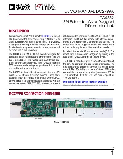
The LTC DC2799A is a demonstration board that uses the LTC4332 to extend a SPI interface with 3 slave devices up to 1200m, or 150m with a 500kHz SCK as factory configured. It is designed to be compatible with the Pmod interface for evaluation with Pmod masters and slaves. The local side interfaces with the host SPI master as four SPI slave devices: three for remote slave devices and one (SSC) for configuring the LTC4332 extenders. The remote side implements a SPI master with 3 slave selects and supports all four SPI modes, with all remote modes set to (0,0) by default.
The board includes Pmod connectors, pluggable terminal blocks for the local-remote link, and pin headers for control and I/O signals. The local and remote side circuits are located on either side of a score, so the board can be physically separated. The link is full-duplex, with A connecting to Y and B connecting to Z, and onboard biasing uses 619Ω pull-up/pull-down resistors and 120Ω terminating resistors.
| SPI extender IC | LTC4332 |
|---|---|
| Link extension | up to 1200 m; 150 m with 500 kHz SCK as factory configured |
| Factory-set maximum SCK frequency | 500 kHz |
| Extended common mode voltage range | 25 V |
| Pmod compatibility | Digilent Pmod Interface Type 2A (expanded SPI) version 1.2.0 |
| Pmod connectors | 12-pin right-angle pin headers, 100 mil spacing |
It can extend a SPI interface with 3 slave devices to up to 1200m, or 150m with a 500kHz SCK as factory configured.
The DC2799A is compatible with the Digilent Pmod Interface Type 2A (expanded SPI) version 1.2.0.
The local side supports either SPI mode (0,0) or (1,1).
All remote side SPI modes are (0,0) by default.