
Integration guide with specifications and PCB layout instructions for the Lantronix xPort Pro embedded device server.
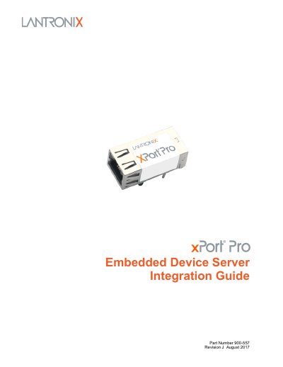
This guide is intended for engineers who need to integrate the Lantronix xPort Pro embedded device server into a custom printed‑circuit board. It covers hardware features, electrical and functional specifications, and recommended PCB layout and grounding practices.
The document includes block diagrams, pin‑out tables, dimensions, LED descriptions, power and temperature limits, as well as compliance information and a 485 connection example. It also references related user guides and software tools for configuration.
| Supply Voltage (VCC) range | 0 V to 3.6 Vdc |
|---|---|
| Operating Temperature | -40 °C to +85 °C |
| CPU | 32‑bit Freescale Coldfire processor |
| SDRAM | 8 MB or 16 MB |
| Flash memory | 16 MB |
| Ethernet interface | 10Base‑T / 100Base‑TX auto‑sensing |
| LED indicators | Link (solid green) and Activity (blinking amber) |
The device is powered from a +3.3 V supply; typical VCC is 3.3 V with a range of 3.15 V to 3.46 V.
The UART can be set from 300 bps up to 921 600 bps, but the standard 460 800 bps rate is not supported.
Yes, each CP pin can be programmed for flow‑control, modem control, or generic I/O functions.
The xPort Pro operates from –40 °C to +85 °C.