
Quick reference guide for Hitachi X200 series inverters covering wiring, keypad operation, powerup test, and error codes.
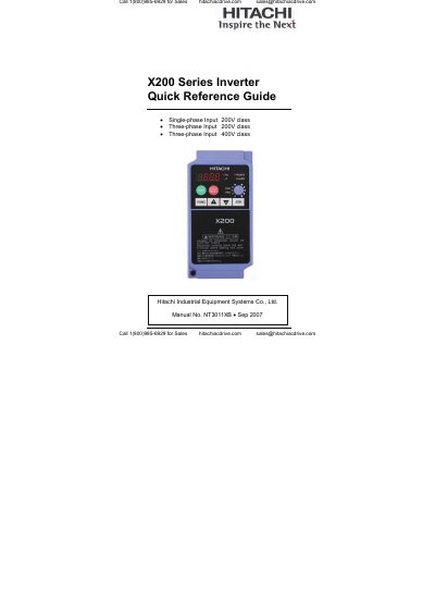
This quick reference guide is for experienced users servicing existing Hitachi X200 series inverter installations. It covers power and control terminal wiring, keypad operation, a basic wiring diagram, and a powerup test procedure.
It also lists basic error codes and trip conditions, and describes how to restore factory default settings. The guide applies to single-phase 200V, three-phase 200V, and three-phase 400V input classes.
| P24 logic supply | 24VDC supply, 30mA max. |
|---|---|
| Discrete logic output | 50mA max. ON current, 27VDC max. OFF voltage |
| Analog voltage output | 0 to 10VDC, 1mA max. |
| Analog current input | 4 to 19.6mA range, 20mA nom. |
| Analog voltage input | 0 to 9.6VDC range, 10VDC nominal, 12VDC max., input impedance 10k Ω |
| +10V analog reference | 10VDC nominal, 10mA max. |
| Alarm relay resistive load | Max resistive load=250VAC, 2.5A; 30VDC 3A; |
| Over-current trip level | Nominally 200% of the rated current |
Press the Stop/Reset key to reset the inverter and clear the error.
E_01 indicates an over current event while at constant speed.
No, analog input O and OI cannot be used at the same time.
Set b084 to 01 to enable initialization.