
The GP2400‑TC41‑24V Touch Panel Unit User Manual provides safety warnings, installation, wiring, maintenance and technical specifications.
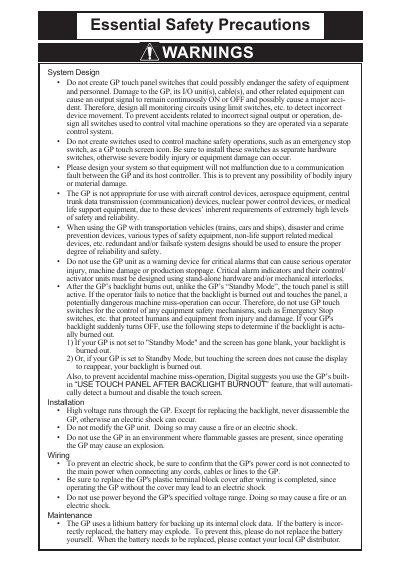
This manual explains the safe use of the GP2400‑TC41‑24V touch panel unit, including warnings about electrical hazards, backlight burnout, and restrictions on use in safety‑critical applications. It also details required grounding, environmental limits, and disposal instructions.
Installation steps cover mounting the unit, securing the gasket, attaching fasteners with the correct torque, and connecting power, serial, Ethernet, printer and expansion interfaces. Wiring guidelines, grounding recommendations, and maintenance procedures such as battery handling and backlight replacement are also included, along with a full list of specifications and part numbers.
| Input voltage | DC24V |
|---|---|
| UL registration model | 2880061 |
| Installation fastener torque | 0.5 N·m |
| Panel thickness | 1.6 mm to 10.0 mm |
| Grounding resistance | 100 Ω |
| Backlight replacement model | PS400‑BU00‑MS |
The unit is designed to use only DC24V input; any other voltage may cause damage.
A torque of 0.5 N·m is required when tightening the installation fasteners.
A grounding resistance of 100 Ω or less is recommended.