
Installation instructions for the Flexco STP-HG-V4 transfer plate kit, covering required tools, parts, positioning, welding and adjustment on conveyor systems.
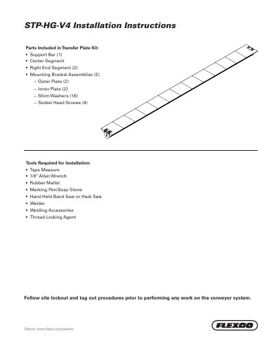
This document is the installation instructions for the Flexco STP-HG-V4 transfer plate kit, a guard/transfer assembly installed in the gap between conveyor pulleys. It lists the tools required for installation, the parts included in the kit (support bar, center and end segments, and mounting bracket assemblies), and step-by-step procedures from measuring and cutting the support bar through final adjustment.
The instructions cover horizontal and staggered positioning of the segments relative to the pulley tangent points, welding of the mounting brackets to the structure, cutting and fitting the final segments, and fine adjustment of the transfer using screws and shim washers. A parts list with item codes and ordering numbers is included, along with Flexco's Downers Grove, Illinois contact details.
| Horizontal (screw) adjustment | 1/8 in (3 mm) total |
|---|---|
| Vertical (shim) adjustment | 1/16 in (1.5 mm) total |
| Recommended segment drop below tangent line | Approx. 1/2 in (13 mm), max 1/4 of pulley diameter |
| Profiled belt clearance | 0.012 in |
| Support bar cut length | 3/8 in (9 mm) less than internal structure width |
Required tools include a tape measure, 1/8" Allen wrench, rubber mallet, marking pen or soap stone, hand held band saw or hack saw, welder with welding accessories, and thread locking agent.
The weld bead must be at least 1/4" from the top of the outer plate, because a weld bead may interfere with end segment installation.
Use a table saw to cut a final segment to 1/16"–1/8" (1.5–3 mm) less than the MAX WIDTH.
Loosening the socket head screws allows 1/8 inch (3 mm) of total horizontal adjustment, and adding or removing shims from the mounting brackets adjusts the transfer up or down a total of 1/16th inch (1.5 mm).