
This manual covers installation, operation, calibration, maintenance, and parts ordering for Fisher 2500 and 2503 pneumatic controllers and transmitters…
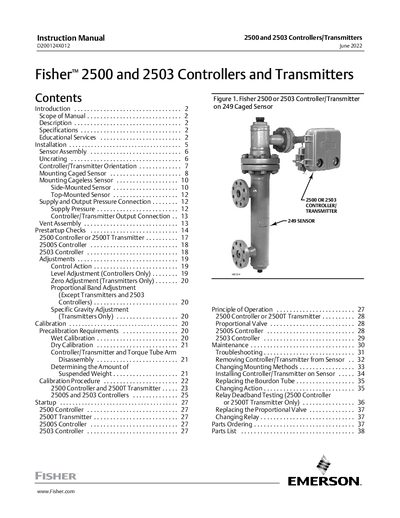
The document serves as an instruction manual for the Fisher 2500 series (including models 2500, 2500C, 2500R, 2500S, and 2500T) and the 2503 controller. These pneumatic devices are designed to control or transmit fluid level, interface levels, or density when used in combination with 249 displacer-type sensors.
The guide provides comprehensive procedures for installation, including sensor assembly and various mounting orientations (caged, cageless, side-mounted, top-mounted). It details operational adjustments such as control action, zero/span settings, and calibration methods. Additionally, the manual includes troubleshooting steps, maintenance instructions like replacing the Bourdon tube or proportional valve, and a parts list for ordering.
| Input Signal Range (Level) | 0 to 100% of displacer length |
|---|---|
| Standard Displacer Lengths | 356 mm or 812 mm (14 inches or 32 inches) |
| Output Signal Range (2500/2500T) | 0.2 to 1 bar (3 to 15 psig) or 0.4 to 2 bar (6 to 30 psig) |
| Independent Linearity (Transmitters only) | 1% of output pressure change |
| Hysteresis | 0.6% of output pressure change |
The supply medium must be air or natural gas that is clean, dry, and noncorrosive.
The full output pressure change is adjustable from 20% to 100% of displacer length.