
User manual for the Exar XR21B1411_SP337 evaluation board, featuring the XR21B1411 USB UART and SP337 programmable serial transceiver.
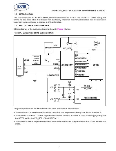
The XR21B1411_SP337 evaluation board is designed to demonstrate the capabilities of Exar devices, including the XR21B1411 enhanced 1-channel USB UART, the SP6260 LDO regulator, and the SP337 programmable serial transceiver.
The board can be configured to operate in different modes, including RS-232 (default), full-duplex RS-485/422, and half-duplex RS-485, using various headers and jumpers.
| USB UART | XR21B1411 (1-channel) |
|---|---|
| LDO Regulator | SP6260 (150mA) |
| Serial Transceiver | SP337 (Programmable RS-232/RS-485/RS-422) |
The DB9 connector (CON1) should not be used when the board is configured for RS-485/422 mode.
The XR21B1411 is an enhanced 1-ch USB UART that can be powered directly from the 5V from VBUS.
It is configured for RS-232 mode when shipped from the factory.
RS-485 mode can be enabled by removing the jumper between 5&6 of J10. Jumpers should also be installed on J10 pins 1&2 and J10 pins 3&4.