
Eaton PEMLD PEM Display Module Mounting Kit instruction manual covering cutout sizes, clearance, mounting, and RJ45 connection to the PEM.
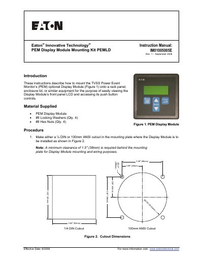
The Eaton PEMLD PEM Display Module Mounting Kit instruction manual explains how to mount the optional PEM Display Module on a rack panel, enclosure lid, or similar equipment so its front-panel LCD can be viewed and push buttons accessed. It lists the supplied display module, four #8 locking washers, and four #8 hex nuts.
The procedure covers making a 1/4 DIN or 100mm ANSI cutout, allowing at least 1.5 in (38 mm) clearance behind the mounting plate, securing the module with the supplied hardware, and connecting it to the PEM with a standard RJ45 patch cable. Eaton recommends a Shielded Twisted Pair CAT-5E RJ45 patch cable no longer than 10 feet and advises routing it separately from system wiring. The document is IM01005005E Rev. 1, September 2006.
| Cutout options | 1/4 DIN or 100mm ANSI |
|---|---|
| Minimum clearance behind mounting plate | 1.5 in (38 mm) |
| Recommended patch cable | Shielded Twisted Pair CAT-5E RJ45, 10 ft maximum |
| Connection type | Standard RJ45 patch cable |
| Supplied locking washers | 4 |
| Supplied hex nuts | 4 |
The module can be installed in either a 1/4 DIN or 100mm ANSI cutout.
Eaton recommends a Shielded Twisted Pair CAT-5E RJ45 patch cable that does not exceed 10 feet.
A minimum clearance of 1.5 inches (38 mm) is required behind the mounting plate.
It is secured with the supplied #8 lock washers and hex nuts.