
This document shows typical application circuits and usage instructions for Dilong's DEM/DSM/DBM/DQM series brick power modules.
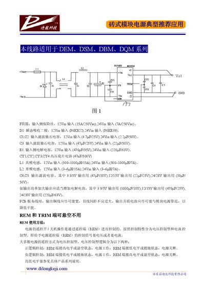
The note describes the recommended input side components for the brick‑type modular power supplies, including input fuses, transient‑voltage‑suppressor diodes, filter capacitors, common‑mode and differential‑mode inductors, and output filtering capacitors. It also gives layout advice such as using wide copper traces and placing output capacitors close to the module to reduce interference.
Remote control (REM) operation and output voltage adjustment (TRIM) are explained. REM uses voltage‑controlled logic (high or low level) to turn the supply on or off, while the TRIM pins allow the output voltage to be fine‑tuned with external resistor networks or potentiometers, supporting both positive and negative logic modes. This manual is written in Chinese.
| Input Fuse Rating | 12 V in 15 A/250 Vac; 24 V in 7 A/250 Vac |
|---|---|
| Input Filter Capacitor C1, C2 | 12 V in 4.7 µF/25 V; 24 V in 2.2 µF/50 V |
| Common‑Mode Inductor L1 | 12 V in 500‑1000 µH/15 A; 24 V in 500‑1000 µH/7 A |
| TRIM Positive‑Logic Adjustment | Connecting resistor to TRIM raises output voltage |
The output voltage can be fine‑tuned via the TRIM pins by adding an external resistor network or potentiometer; positive‑logic raises the voltage, negative‑logic lowers it.