
This user guide provides operating instructions, hardware details, and calibration data for the ADL9006-EVALZ evaluation board.
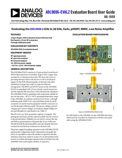
The ADL9006-EVALZ is a 2-layer Rogers 4350 evaluation board featuring an aluminum heat sink and 2.9 mm RF connectors, designed to evaluate the ADL9006 2 GHz to 28 GHz GaAs pHEMT MMIC low noise amplifier. The board includes a through calibration path between J5 and J6 connectors to account for trace losses and is populated with components suitable for the device's full operating temperature range of -40°C to +85°C.
To operate the board, a 5 V, 200 mA power supply must be connected to the VDD header, and an optional -2.0 V to +2.6 V, 100 mA supply is required for the VGG2 header to control gain. The guide details the board's hardware connections, provides a schematic and assembly drawing, and lists insertion loss and return loss data for the through calibration path across the frequency spectrum.
| Frequency Range | 2 GHz to 28 GHz |
|---|---|
| Operating Temperature | -40°C to +85°C |
| RF Connector Type | 2.9 mm, female coaxial |
| RF Trace Impedance | 50 Ω |
| PCB Material | Rogers 4350 |
| Power Supply Requirement | 5 V, 200 mA |
| Gate Control Voltage | -2.0 V to +2.6 V |
You need an RF signal generator, an RF spectrum analyzer, an RF network analyzer, and two power supplies (5 V and -2.6 V to +2.6 V).
They provide a through calibration path (THRU CAL) to calibrate out board trace losses.