
Allen-Bradley PowerFlex 700 Frames 7-10 Installation Instructions

Installation and basic start-up instructions for Allen-Bradley PowerFlex 700 Adjustable Frequency AC Drives, Frames 7 through 10.
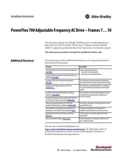

Allen-Bradley PowerFlex 700 Frames 7-10 Installation Instructions - cover page
Brand
Allen-Bradley
Category
Industrial Robot
Document type
Installation Guide
Language
English
Pages
76
File format
PDF
File size
5.5 MB
Published
23 October, 2026
Updated
23 October, 2026
MD5 checksum
EF150055251BB42A44E11457A1BEE4F2

About this manual

This document provides installation instructions and basic startup procedures for the PowerFlex 700 Adjustable Frequency AC Drive, specifically for Frames 7 through 10. It is intended for qualified installers and covers the five basic steps required to install and perform a Basic Start-Up of the drive. A Human Interface Module (HIM) is required to perform the Basic Start-Up routine covered in this manual.

What's inside

  • Step 1: Read the Precautions and General Information
  • EMC Compliance
  • Component Locations
  • Step 2: Lifting and Mounting the Drive
  • Step 3: Wire the Drive
  • Step 4: I/O Wiring
  • Step 5: Start-Up Check List
  • Troubleshooting

Frequently asked questions

What voltage ratings are supported for CE certification on Frames 7 through 10?

Frame 7 through 10 drives are CE Certified for use with 400V AC and 480V AC center grounded neutral power supply systems only.

What is the maximum current rating for the TB11 terminal block?

The TB11 terminal block has a maximum rating of 25 amperes RMS.

What type of wire must be used for the +DC and -DC terminals?

You must use 75 °C copper wire only to connect the +DC and -DC terminals.

Download PDF (5.5 MB)

More Allen-Bradley Manuals


View all Allen-Bradley manuals →